| Lesson 1 | Lesson 2 | Lesson 3 | Lesson 4 | Lesson 5 | Lesson 6 | Lesson 7 | Lesson 8 | Assessment guidance | Homework Tasks |
PIC Circuits
1 Introduction.
What are PIC chips?
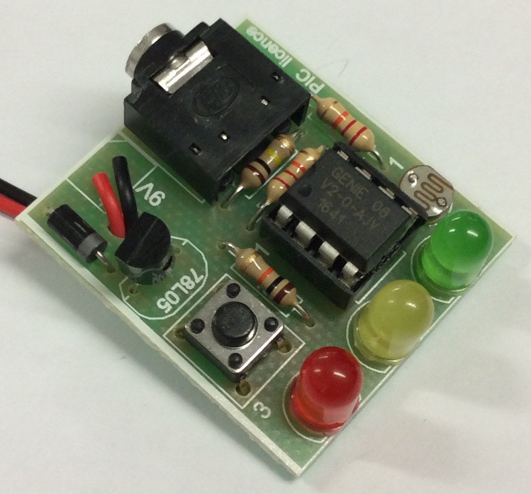
Peripheral Interface Controllers are small silicon chips which can be programmed to perform useful tasks. In school, we tend to use Genie branded chips, like the 08 model you will use in this project. Others (e.g. PICAXE) are available. PIC chips allow you connect different inputs (e.g. switches) and outputs (e.g. LEDs, motors and speakers), and to control them using flowcharts. Chips such as these can be found everywhere in consumer electronic products, from toasters to cars.
While they might not look like much, there is more computational power in a single PIC chip used in school than there was in the space shuttle that went to the moon in the 60's!
When would I use a PIC chip?
Imagine you wanted to make a flashing bike light; using an LED and a switch alone, you'd need to manually push and release the button to get the flashing effect. A PIC chip could be programmed to turn the LED off and on once a second. In a board game, you might want to have an electronic dice to roll numbers from 1 to 6 for you. In a car, a circuit is needed to ensure that the airbags only deploy when there is a sudden change in speed, AND the passenger is wearing their seatbelt, AND the front or rear bumper has been struck. PIC chips can carry out their instructions very quickly, performing around 1000 instructions per second - as such, they can react far more quickly than a person can.
2 Getting started with PIC circuit design.
Design time
- Open up Circuit Wizard, and create the following circuit layout. Before you do, you will need to open a new file.
- Always select "Circuit With GENIE Flowchart"

- The Genie 08 chip can be found in the "Microcontrollers" drop-down menu item.
- the battery can be found in the "Power Supplies" drop-down menu (right at the top).
- the LED can be found in the "Light Emitting Diodes" drop-down menu, be careful not to choose the "diode" option.

- To rotate the LED, first select the component (LED in this case) then click on the rotate left/right buttons at the top of the page - see image below.


- Once complete, create a new folder in your home drive - Design Engineering\Year8\PIC folder. Now save the file as "FirstPIC" in your Design Engineering\Year8\PIC folder.
- Whether its an LED or a PIC chips, the first thing that electronic components need is power, and a connection to ground. Circuit Wizard simplifies this for us by showing each of the 8 legs of the PIC (known as pins) in a different order to how they really are. This makes drawing the initial circuit easier. In this case, Power has been drawn by itself at the top of the chip, and the ground pin (the negative end of a battery) is at the bottom.
- When designing PIC circuits, Inputs are placed to the left of the PIC chip. We're not going to worry about these for now.
- Outputs are placed to the right of the PIC chip. In the project you're making, you'll actually use 3 LEDs, connected to the other output pins. For now, we can just leave outputs 2 and 4 empty.
- One of great things about the Genie 08 PIC is that you can change the configuration of the pins; this will allow users to re-configure the PIC different projects.
- Below is how you would go about doing this.
- In this project, we are not going to change these settings.

- Try and run the circuit (Click on the 'play' button). You'll see an error message, and the screen will change to show you a green flowchart symbol with the word, "Start" in it. This is because the PIC chip needs you to give it instructions as to what you'd like it to do. Using shapes located on the right-hand side of the screen and experimenting with clicking near the shapes you've drawn, create the following flowchart. We're going to make the LED blink on and off.

- If you had to guess, you could probably figure out that instructions are followed starting from "Start", and following the arrows to the bottom, before being started all over again endlessly. If you've tried to run the program, you'll see that its still not sure what you'd like it to do.
- Before it can run, the PIC chip needs a little more information. Which output(s) are we turning on? How long are we to wait for?

- Double click on the top parallelogram (the top output shape), and slowly click twice on the faint letter 'x' that is just underneath output 0 until it turns green, then click "Ok".
- Repeat for the other output shape, but this time click only once to turn it to "0".
- Finally, double-click on each of the "Wait" shapes, and type "2" in the time boxes.
- Time to test your first PIC circuit. Click the, "Circuit Diagram" tab in the bottom-left-hand corner of the Circuit Wizard window, then click the play icon to start the simulation. Your program is now working as follows:
1. Turn on output 0 (the LED),
2. Wait 2 seconds,
3. Turn off output 0 (the LED),
4. Wait 2 seconds,
5. Go to line 1.
Coding time
- Open a .doc (Word document). You will screenshot all the steps here and answer the questions.
- Try and modify your program. You'll be saving this circuit in your home drive later.
- Make the LED blink on and off twice as quickly. Now screenshot the flowchart and paste it into the Word document.
- Why are there two wait shapes, and not just one? Answer this question in the Word document.
- Modify your program, so that it comes on for 2s, off for 1s, on for 1s and off for 2s before repeating. Now screenshot the flowchart and paste it into the Word document.
- Modify your program so that the LED comes on for 3s ONCE, then blinks steadily on and off once a second until the program is stopped. Now screenshot the flowchart and paste it into the Word document
- Save your text file as "First Badge" in your Design Engineering\Year8\PIC folder.
- Now go back and save the original Circuit Wizard file as "SecondPic", so that you can make the next set of changes and still have a backup.
Quiz Time
- Complete the quiz for badge.
- Click on this link to complete the quiz.
- You need to also upload screenshots of your code/flowchart files.