1 Introduction
Learn It
In this project we examine one of the most valuable circuits to be invented - the flip flop. Originally it was designed with VALVES, along with its simpler version (without the two capacitors - called a bi-stable Multivibrator), it was realised it could store a "bit" of information. The bi-stable Multivibrator circuit required an input pulse to the left side of the circuit and the load (say a globe) stayed ON when the signal was removed. A pulse to the other side of the circuit turned the globe OFF. This was the first time an electronic circuit had stored a "piece of information." This was the beginning of the COMPUTER AGE.
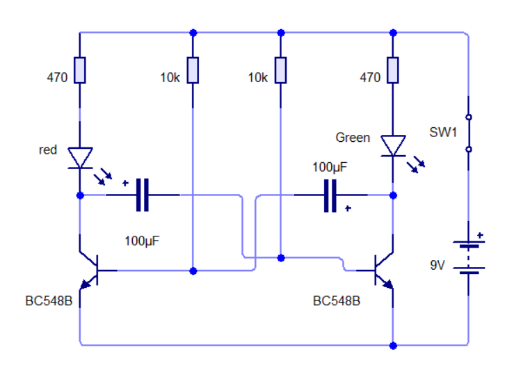
The Flip Flop is a symmetrical arrangement using two transistors with cross-coupling. Each transistor has a base bias resistor (10k in our case) and a LED with 470 resistor in the collector lead to form the collector load.
The circuit consists of two identical halves and is called a Flip Flop because one half is ON while the other half is OFF. The ON half is keeping the OFF half OFF but it cannot keep it off indefinitely and gradually the OFF half turns ON via the 10k base-bias resistor. This drives the ON side OFF and the circuit changes state. In other words it flips over. The same events occur in the other half of the cycle and the circuit eventually flops back again.
This sounds very complicated but in reality the circuit is quite simple in operation as one half is exactly the same as the other and there are only 5 components in each half.
Want to know more? Click here:
Design It
Open Circuit Wizard and make the circuit below:
You will need 2 transistors, 2 LEDs, 4 resistors, 2 capacitors, a SPST (latching) switch and 9V battery.
Now you need to make the circuit into a PCB.
Click the Circuit Wizard button > Next > Single thin > Tick 'Allow me to customised' option > next > next> convert
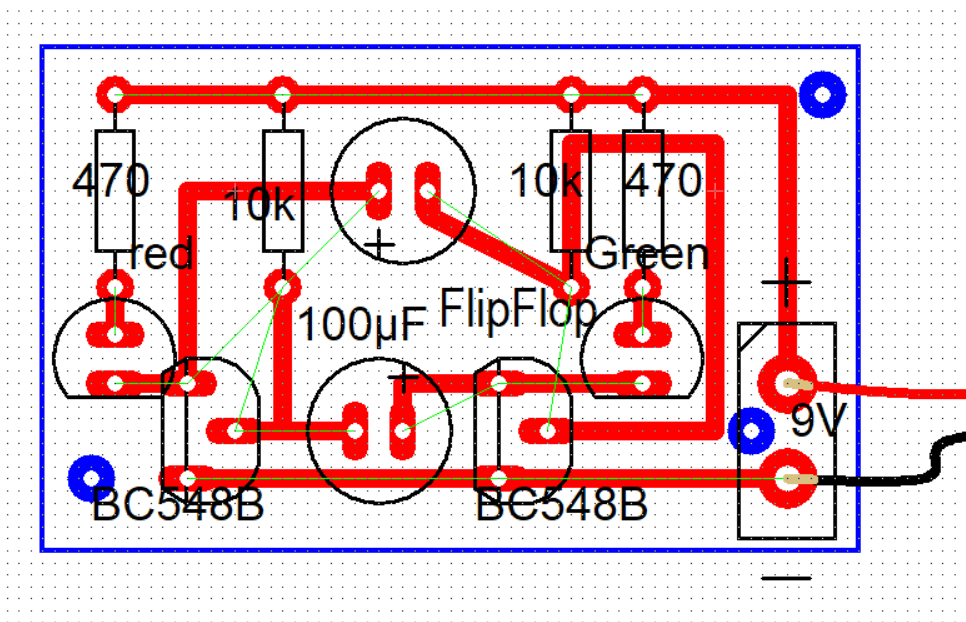
Now click normal and move the components into place and connect the tracks. Finally add an off board power supply > last battery 9V and see if it works.
It should look like this:
Build It
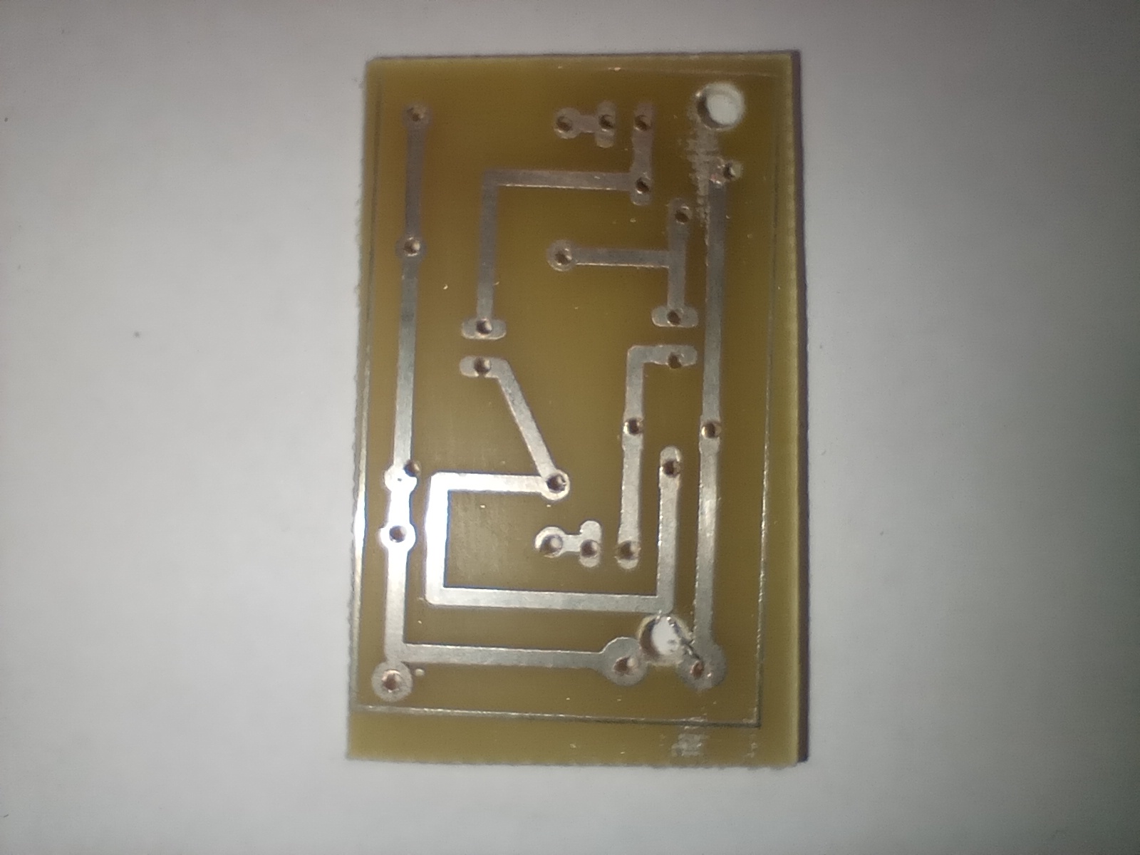
Firstly we need to drill. Ask the technician for the FlipFlop PCB. Now use the 1mm precision drill to drill ALL the holes. Make sure you are wearing goggles.
Secondly use the bench pillar drill with a 3mm bit to drill the three larger holes. These can be identified as they do not connect to anything else. Alternatively, they are in blue on the above PCB design.
Now it is time to solder.
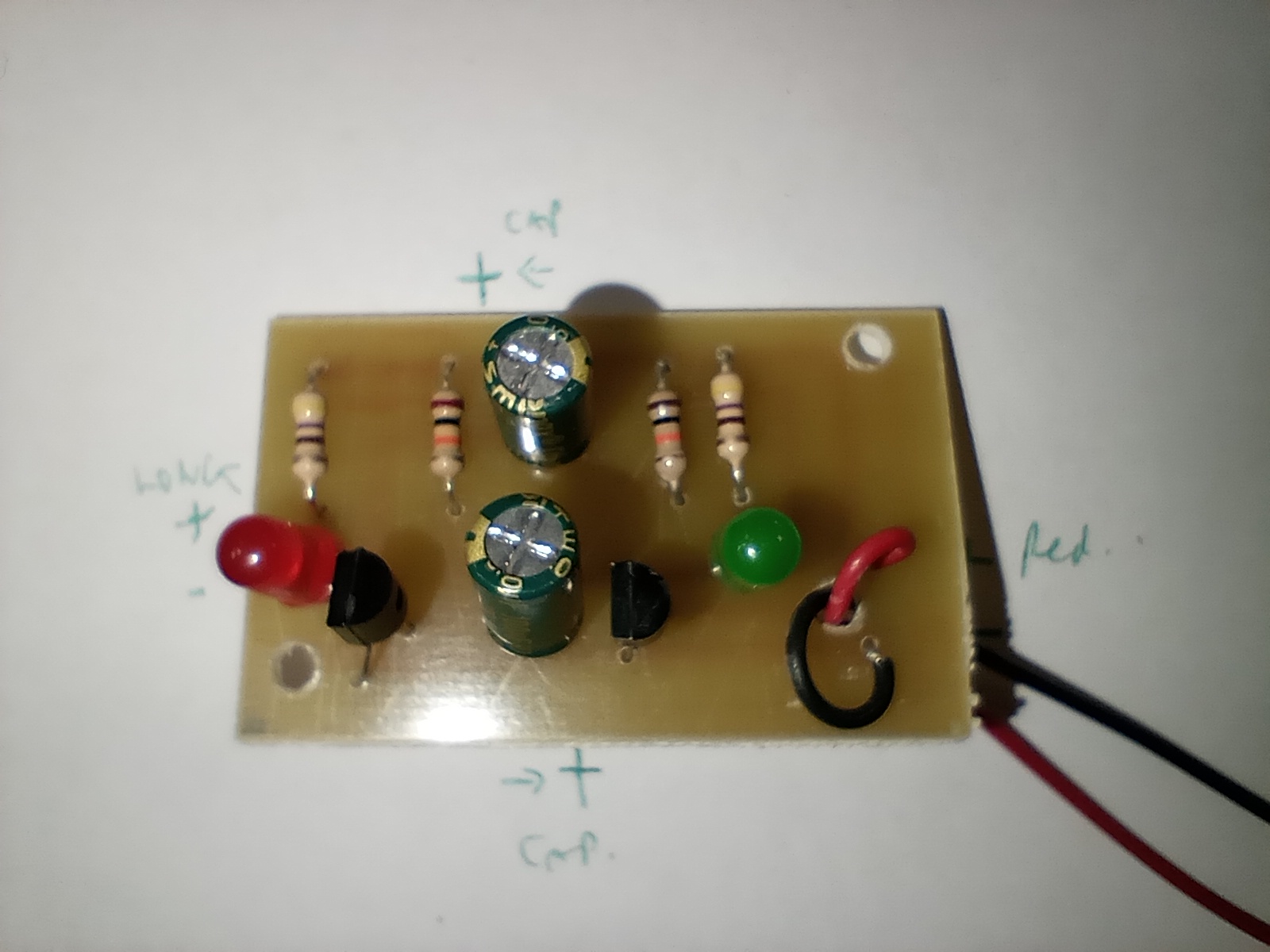
You will need 4 resistors, 2 capacitors, 2 transistors, 2 LEDs and a power cable. Please note that all the components, except for the resistors, need to be in the correct orientation. Check the photo below and the labels to help you.