You're going to have a go at creating a PCB of your circuit.
First, you will need to open the circuit you designed from week 3. Make sure you delete the virtual multimeter.
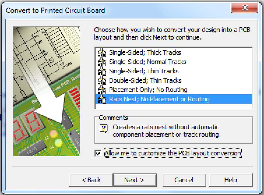
Click the button that looks like this at the top of the workspace.
Click Next and then choose Rats Nest; No Placement or Routingand check the box for allowing customisation.
Next and Next again
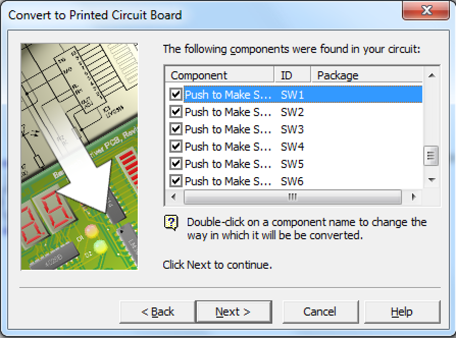
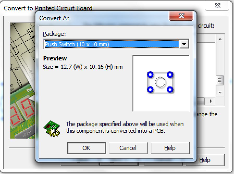
For each of the PTM switches, you need to make sure you're choosing 10x10 switches. Double click the switch in the list and change it.
Now you can click through the remaining menus and convert your circuit to a PCB, this is done by clicking on next, until you get to finish.
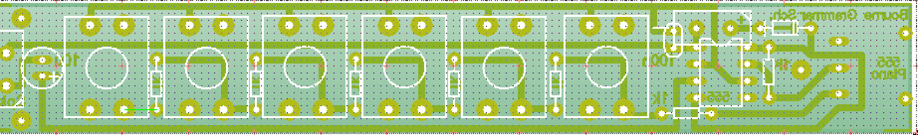
You'll need to try and place the components so that the green connecting wires don't overlap. You might find it's easier to delete the rectangular board to begin with.
Once you are happy with the placement, try and connect up the components with tracks.
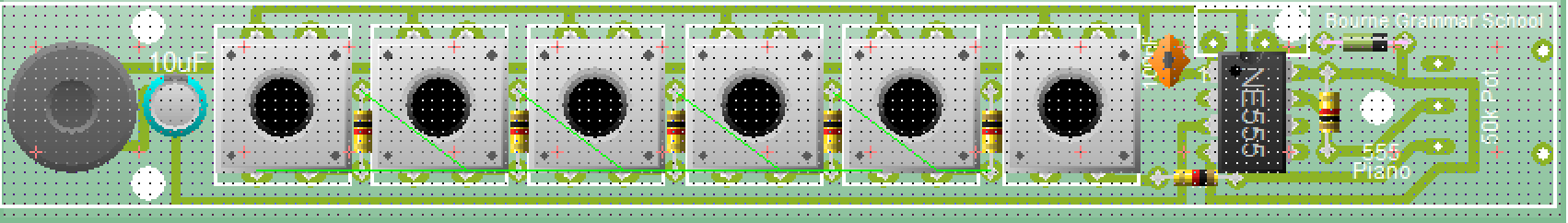
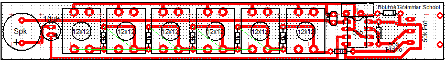
Here's an example, but try and design your own.
Please note: The potentiometer (variable resistor) looks different to the example below, but if you follow the green lines, you will be able to do it.
Badge It - Silver
Add the image of the PCB to your write up.
Explain any placements that you found tricky to solve.
Upload your work to BourneToLearn.com
Design the case
You're going to have a go at creating a case to house your instrument.
Here are some tips to help you:
The PCB is 20 mm by 150 mm and 2 mm thick.
You can use fly leads to extend the buttons, the speaker or potentiometer to increase the flexible of your design.
You either Solidworks or 2D Design to make your case.
You may need a pencil and paper sketch to get you started.
You need to think about the parts that are going to fit together to make your instrument.
Think about ergonomics, how are you going to play your 'sweet' tunes?
Design It
We're going to use Solidworks to design our instrument.
Hopefully you have already had lots of experience with Solidworks last year, so for this recap section of the project, you'll just be creating a couple of the Solidworks parts and assembling them.
In Solidworks you start by creating a 2D sketch. You can then convert this to a 3D part. You can then join parts together to make a 3D assembly.
Try It
In Solidworks you have to ensure all your drawings are fully defined.
This means that the software must know the dimensions of every line you draw.
Quite often the software is able to work out a dimension of a line, from others you have provided.
Video of building two parts of the case
Video of mating
Video of converting Solidworks to 2D Design for laser cutting
Badge It - Gold
Upload a screenshot of some parts for your instrument and to BourneToLearn.com.
Badge It - Platinum
Upload a screenshot of your fully designed instrument to BourneToLearn.com.